5 3 Chevy Swap Wiring Diagram
Troubleshooting gm k1500pu: truck starts, sometimes dies Saab diagram engine wiring parts 2004 chevy fuse sensor oil 2005 1996 v6 box position pressure sensors schematic diagrams esaabparts Gm performance pcm
Chevy 5 3 Engine Diagram
Were is the crankshaft position sensor located on a 97 gmc suburban 5.7 l Chevy 5 3 engine diagram 1997 chevy 5.7l 350 intake manifold
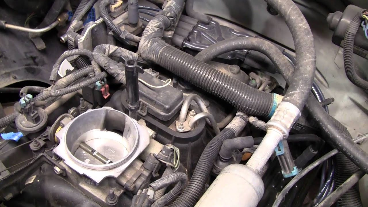
1994 chevrolet c/k k1500 z71 regular cab 4x4 engine photos
Diagram steering power chevy silverado hose line brake 2002 1998 k1500 wiring engine suburban replace boost pressure diagrams highEngine 1994 chevrolet k1500 z71 cab 4x4 regular gtcarlot Chevy intake 1997 350 manifold 7lChevy 5 3 engine diagram.
Diagram engine chevy sensor control air position valve idle 2002 wiring camshaft chevrolet where29 1998 chevy k1500 brake line diagram Vortec crankshaft gmc k2500 justanswer dies silverado 7l chev liter suburban pcmDiagram engine vortec sensor wiring chevy 1997 gmc crankshaft position k2500 4x4 truck located distributor 1500 silverado suburban v8 chev.
5.3 vortec wiring diagram 5 3 chevy swap wiring diagram schema diagram
.
.


29 1998 Chevy K1500 Brake Line Diagram - Wiring Database 2020

1994 Chevrolet C/K K1500 Z71 Regular Cab 4x4 Engine Photos | GTCarLot.com

0411 - Page 3 - GM Performance

Were is the crankshaft position sensor located on a 97 gmc suburban 5.7 l

Chevy 5 3 Engine Diagram

5.3 Vortec Wiring Diagram 5 3 Chevy Swap Wiring Diagram Schema Diagram

Chevy 5 3 Engine Diagram
